Ever since the caveman crouched over his fire in his cave to keep himself warm, man has continued his quest to improve the comfort of his environment. Today a variety of heating methods exist to condition warm or cool the building space that we are in, based upon the same age old fundamental laws of heat transfer that move warmth from the thermal source to the body space.
In building spaces, heat is transferred by convection or radiation. Furnaces, rooftop or unit heaters and air rotation are examples of convective heat transfer. Infrared heat is radiant heat transfer and is commonly accomplished with gas fired low intensity tube heaters or open flame ceramic face high intensity heaters.
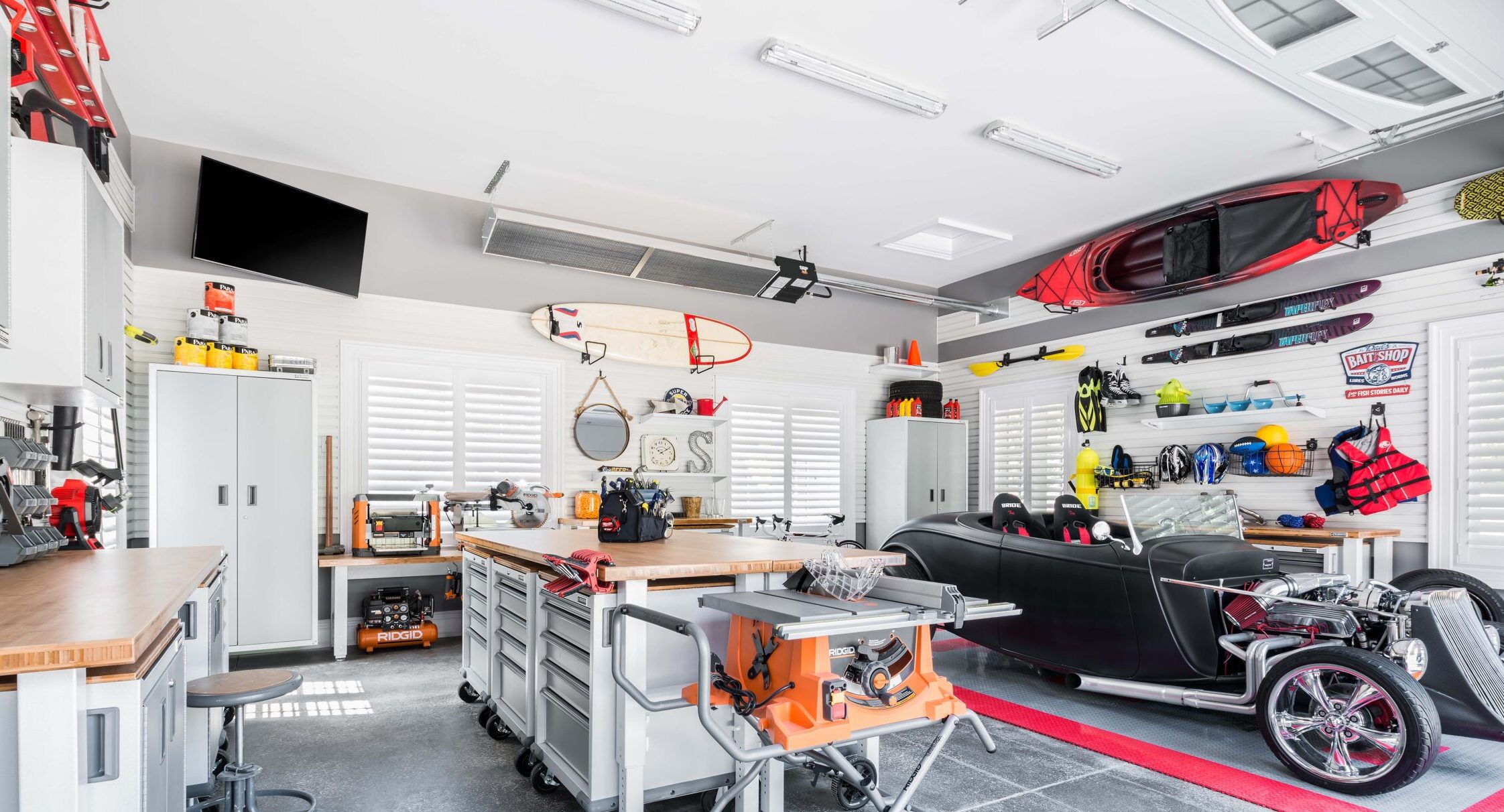
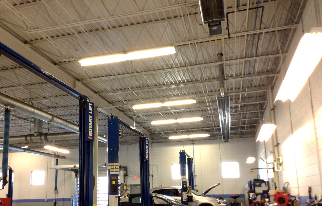
Advantages of warm air systems are: a centralized thermal source and flexibility in ducting the warm air to precisely where it is wanted. Also, conditioning equipment can easily be incorporated in the ducting system. Some disadvantages are: noise, stratification, dust circulation and upper end operating cost, especially in larger “box building” structures.
![]()
Infrared heat addresses most of these deficiencies but has often been rejected because a lack of good layout practice has resulted in poor heat distribution.
Fortunately, our understanding of how infrared radiant heat works and some technical improvements in equipment make low intensity infrared heat the preferred option for industrial building heat, providing comfort and operating economy.
![]()
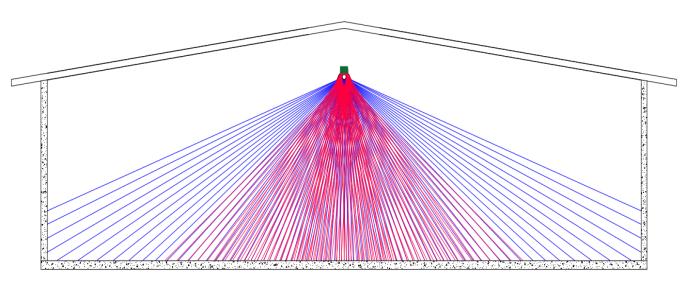
Infrared heaters keep people warm via direct and secondary thermal mechanisms. The heater produces infrared energy which radiates down on people and objects, the former absorb the energy and convert it to body heat directly, as though being warmed by the sun. The radiant energy that strikes the floor, walls and other objects in the building is absorbed and these objects, as they get warmer, re-radiate thermal energy. This mechanism is the same as the warming of the atmosphere after the earth has absorbed the sunshine.
Heater Placement – Put the heat where the cold is
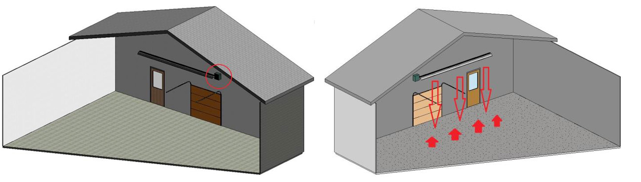
In placing radiant tube heaters in a building layout, it is important to understand that people are uncomfortable when the radiant output of their surroundings is not neutral. Where there are cold walls or windows people will sense a draft unless these areas are heated to the point where they are no longer heat sinks within the space.
Buildings rarely lose their heat evenly over all of the areas. Doors and windows are usually colder, the north side of the building may be subjected to more wind etc. As people move about within the building, they will sense these colder areas because the radiant environment is not neutral.
Conventional radiant tube heaters have a hot and a cooler end which is often considered to be a disadvantage in achieving even heat distribution. However, matching the hotter end of the heater with the colder areas of the building will put more direct radiant on walls, floors and people where there is the most heat loss, evening out heat distribution.
Rule #1: Place the heater with the burner end near doors or colder walls of the building.
Maximize the Thermal Mass
Objects within the path of the direct radiant energy from the heater absorb this energy and re-radiate into the surrounding air.
Different materials have a varying ability to absorb direct radiant energy. For example, air is a poor absorber; steel, wood and cardboard are moderately good absorbers, but concrete is an excellent absorber of infrared energy. Because most building construction incorporates a concrete floor, we have an ideal thermal mass or a thermal “storage tank”. When there is surplus heat it absorbs and stores. When there is a lack of heat (a door is opened or there is an unnaturally cold night ) the thermal mass releases its heat and radiates it to other materials in the building space. Designing the thermal mass concept into a radiant heat layout greatly improves even temperature and heat distribution.
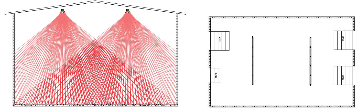
Rule #2: Place a heater so that it sees a maximum amount of concrete floor.
Go Short and High
Low intensity infrared tube heaters come in a variety of firing rates, generally from about 50,000 BTUH to 220,000 BTUH with a manufacturer’s recommended emitter length for a given rate. Given a total building’s heat loss to match, the reaction of many designers is to choose equipment that will be long enough to “cover” the entire floor area – a decision which is not always the best.
All approved radiant tube heaters have passed minimum thermal efficiency tests outlined by ANSI standards and these require that maximum tube temperatures cannot exceed 1100 °F plus ambient and flue gas temperatures cannot exceed 400 °F plus ambient. Adding emitter tube length for the sake of coverage will reduce the flue gas temperature but will only marginally increase the total radiant output since infrared output is a fourth power function of temperature. As a general rule of thumb, a ten foot piece of four inch diameter emitter tube at 250 °F will emit about 5000 BTUH of heat energy, almost all of which will simply rise to the ceiling.
Another negative aspect of stretching emitter tube length is the risk of reaching the flue gas dew point at which time acidic condensate forms which can lead to premature corrosion failure.
Also, stretching out the heater and lowering its flue end temperature even further tends to exaggerate the end-to-end temperature differential and decrease the perceived people comfort.
Insisting on complete radiant coverage of the floor area fails to recognize the ability of the concrete mass of the floor to even out thermal re-release and it does not take into consideration that there is some scatter of the direct infrared rays.
In light of the foregoing, it is important to hang heaters as high as possible to maximize the size of the radiant footprint on the floor while keeping in mind that direct infrared energy that hits high up on outside walls is generally lost energy. Move the heater further towards the center of the building to avoid this.
Rule #3: Where rate and other performance criteria are equal, choose heaters that are shorter rather than longer and hang them as high as possible. This will maximize return on your capital cost and will extend equipment life without reducing efficiency or performance.
Maximize Radiant Efficiency
As stated earlier, all approved infrared radiant heaters have met the same minimum thermal efficiency criteria and while these efficiencies can be increased by adding emitter lengths, any improvement in performance is marginal at best and outweighed by negative factors. Indeed, thermal efficiency is a misleading method of measuring an infrared heater’s performance when the thing that really matters is; “how much energy is reaching the floor and the occupants in relation to the fuel expended?” That is, what is the heater’s radiant efficiency?
Unfortunately, there is no simple answer to this question. The physical configuration of low intensity tube heaters has defied a standardized method of measuring radiant efficiency. Even the methodology used for high intensity heaters is largely flawed. Some common sense analogies may help us to understand the factors that will maximize the radiant efficiency of a heater, without necessarily determining an actual numeric value. A recent incident will help our understanding.
Manufacturer A was concerned with market inroads being achieved by Manufacturer B and so they undertook to compare the two competing heaters in their test facility. Of the two heaters, A had a marginally higher output rate and a marginally higher thermal efficiency. The heaters were the same length. Each of the heaters was operated for the same period and the rise in temperature on a floor grid pattern was noted. Contrary to initial expectations, heater B put more heat into the floor than heater A, and heat at the floor is in practical terms the only thing the user is concerned with.
In reviewing the two pieces of equipment it was ascertained that the only important difference in the two heaters that could have affected these results was reflector design. Heater B was equipped with reflector end caps and had a deep-dish multifaceted aluminum reflector while heater A had a much shallower and very simple “top-hat” design.
The results become even more evident when a ridiculous hypothesis is formulated and answered.
All heaters have round emitters (usually 4 inches in diameter) and the infrared energy is emitted radially.
How efficient would a heater be if there was no reflector? Clearly, all radiant output not reaching the floor would normally not contribute to heating the space, so about 30%. How efficient would a heater be if it were equipped with a perfectly parabolic reflector that focused and reflected ALL the emitted energy to the floor? Baring convective losses, 100% of the emitted radiant energy would reach the floor and contribute to heating the space.
The foregoing analogies arrive at an obvious conclusion.
Rule #4: To maximize radiant efficiency, choose deep, well-engineered reflectors, which reflect a maximum of emitted energy to the floor in a tight pattern. In addition, end caps assist in maintaining emitter temperature and reducing convective loss.
Matching the Heat Load
The design of any heating system must begin with a calculation of the expected heat load. Based on building design, its use and local of weather statistics, the ASHRAE formulae will fairly accurately predict the amount of heat required to maintain building space comfort. While designers are aware that the most efficient heating system is one that provides, on a continuous basis, only sufficient heat to meet current heat loss, they also recognize that weather extremes beyond the statistics do happen and they would rather be faulted for over sizing than under sizing. Heating systems rarely operate beyond 75-80% of their maximum capacity.
Furthermore, it is poorly understood that different methods of heating have inherently different effectiveness. Thermal efficiencies for furnaces and unit heaters are understood, ranging normally from 80-85%. Boiler thermal efficiencies go as high as 90%, and these values are usually incorporated into heating design calculations. However, transfer efficiencies of convectors/radiators and infrared radiant heaters are not understood as well and therefore often ignored.
No factor is included in the calculation for thermal efficiency of the equipment but a factor for radiant transfer is included. This factor is normally a gain of 5-15% in efficiency. Therefore, to design a radiant heating system, a typical ASHRAE degree day calculation is done but the matching system capacity may be downsized 5-15%.
High intensity heaters are adapted more to spot heating, relying on rapid recovery by delivering a high degree of direct radiant. Extra heat allowance must be made for ventilation of the flue gases. Therefore increased performance factors are never greater than 5%. Equipment efficiency factors for low intensity, where some systems can achieve thermal efficiencies of in the low 80% range, can rise to 15% and 20%.
Over sizing a radiant heating system rarely adversely affects the equipment itself, but the more frequent cycling of an oversized system will decrease personal comfort and fuel economy.
Rule #5: To size a low intensity radiant system by Superior Radiant Products, calculate a building heat loss by conventional ASHRAE methods and match the system input capacity to 80-90% of the former. To maximize comfort and fuel economy, do not oversize the heating system.
New Technologies
While good layout practice accomplishes much towards optimum personal comfort and maximum fuel cost savings, some recent equipment design innovations have made further improvements in comfort control.
A common complaint about traditional low intensity infrared heaters is the relatively large variance of radiant output from end to end of the heater. This operating condition has kept this equipment away from applications involving higher people occupancy and low ceilings, where this is particularly noticeable. This deficiency has been addressed by the introduction of the L Series heaters by Superior Radiant Products. By modifying the air flow through the burner and by using different materials along the emitter length, the radiant output variance of the heater is kept at less than 15%.
Theoretically, ideal comfort conditions and maximum fuel economy are achieved by the heating system if it responds exactly and continuously to the building heat loss. Traditional heating systems, infrared included, of course do not do this. The system can only operate at OFF or maximum ON and depends on a thermostat to keep the space temperature normally at the desired setting.
Unfortunately this is inefficient from two perspectives. During the spring and fall periods, the system is obviously oversized to meet exterior conditions. To produce small quantities of heat the system will operate at maximum-ON for very short periods of time and OFF for long periods of time. Each on cycle startup wastes fuel to get the equipment to its operating temperature and then the thermal momentum of the system and tolerances within the thermostat will make the system overshoot its setting at every cycle. The more frequent the cycle, the more fuel is wasted.
Furthermore, this cycling and the condition of maximum burner rate at low heat demand is uncomfortable for occupants.
The foregoing is figuratively described by Chart 1.
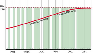
Chart I Conventional Technology Maximum – On / Off
Two stage variable heaters have been available for a number of years and improve the deficiencies described. A two stage thermostat signals the heater to operate at about 75% of its maximum capacity until the heater cannot keep up with building heat loss and the maximum burner rate is signaled to commence. Chart II figuratively describes this. Variable rate heaters improve comfort conditions in off-season, and by running longer for each cycle some fuel savings may be achieved.
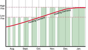
Chart II – Standard Hi-Lo Technology
Written by:
Eric Willms, P. Eng.
Past President of Superior Radiant Products Ltd.
Past Chairman of CSA Joint Sub-Committee on Infrared Heaters